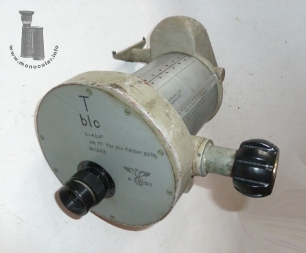
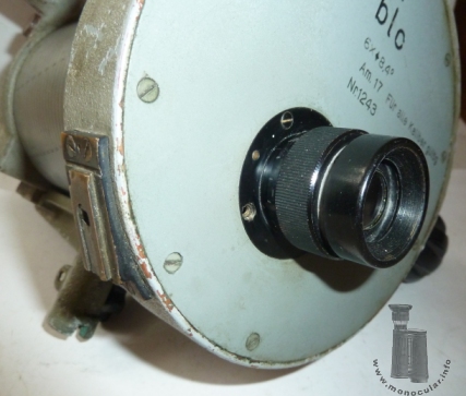
blc AM17 6x
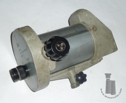
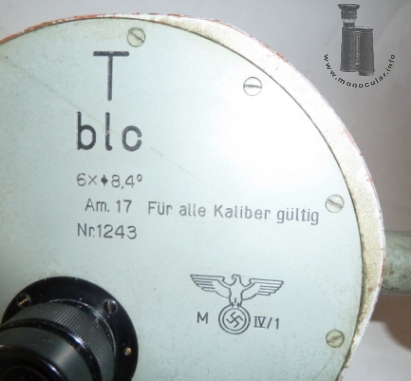
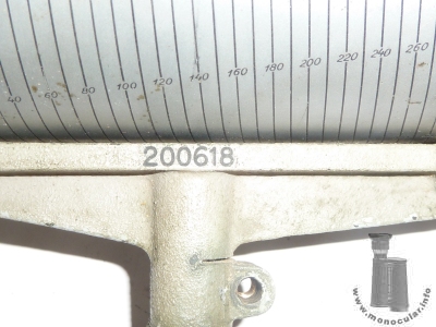
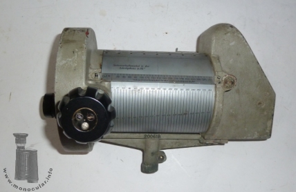
| Der Auswanderungsmesser "AM17" wurde von Zeiss schon seit ca. 1916/17 gebaut - z.B. Modellname "Peres" - und dient als optisches Messgerät zum Berechnen des Schussvorhalts bei der Flugabwehr. Benötigt werden neben dem optischen Auswanderungsmesser eine Stoppuhr und ein Kommadorechengerät (s. Abbildung aus Zeiss Archiv und F. Auerbach, 1925, S. 94). Das vorliegende Exemplar ist mit "blc" gekennzeichnet, also er Zeiss-Codierung aus dem 2. Weltkrieg, sowie mit "T" für höhere Transparenz durch Vergütung (und/oder weniger Luft-Glas-Übergänge) und außerdem mit dem Modellnamen sowie "Für alle Kaliber gültig". Der 8fach verschraubte Deckel ist darüber hinaus mit dem Hoheitskennzeichen des 3. Reichs markiert und mit den optischen Daten "6x ♦ 8,4°" beschriftet. Die Raute wurde bei Zeiss bei einigen militärischen Optiken verwendet. Die graue Lackierung und "M" könnte ein Hinweis auf die Benutzung bei der Marine/Küstenflugabwehr hinweisen. Die Gerätenummer 1243 am Deckel und die Produktionsnummer 200618 am Stativsteg sind Folgenummern zum AM17, welches hier gezeigt wird. | The AM17 (Auswanderungsmesser ≈ deviation meter / lead computer) was made by Zeiss since 1916/17 - e.g. model "Peres". It works as an optical range measurer to calculate fire suspension for anti-aircraft services. It is used together with a stop watch and a commando disc (computing device) (cf. pictures from the Zeiss archive and in Auerbach, 1925, p. 94). The specimen here is marked "blc", the WWII code for Zeiss, and "T" for transparency achieved by coating or less air-glass surfaces. The inscription also state the model name and "valid for all calibres" as well as "6x ♦ 8,4°", thus giving power and field of view. The diamond was sometimes used by Zeiss on military instruments. The top cover has 8 screws. Moreover the cover plate bears the 3rd Reich insignia. An "M" letter and the grey finish may hint to a use by the Navy or coast AA guard. The instrument number 1243 on the cover and the production number 200618 on the tripod rod are successive numbers to the model shown here. |
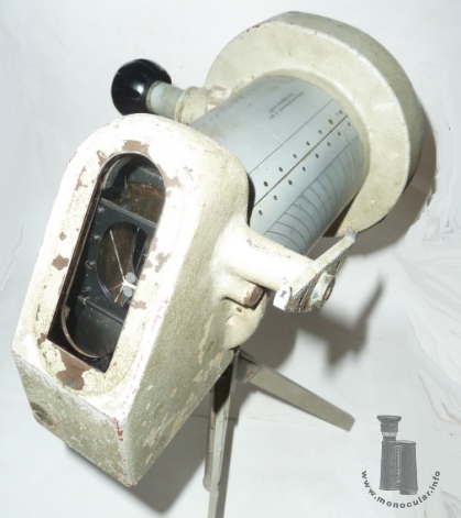
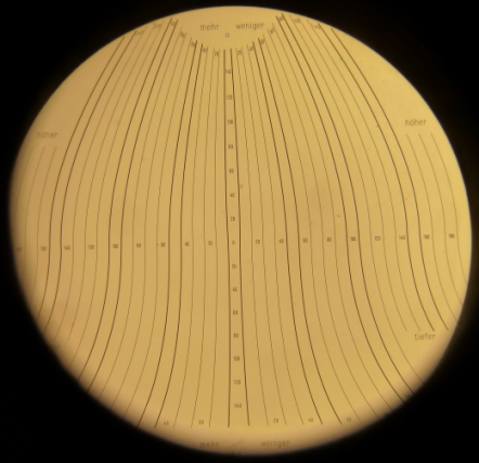
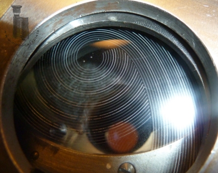
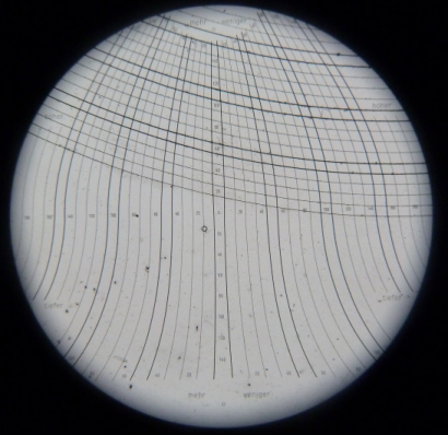
| Der AM17 hat eine feste Strichplatte im Okular mit Dioptrienausgleich und eine weitere rotierende Strichplatte im flachen runden Okulargehäuse zwischen Okular und Prismensystem (evtl. ein Abbe-König Prisma). Die Drehung der 2. Strichplatte mit spiralförmigen Strichen ist mit der Drehung der Messskalentrommel am Gehäuse gekoppelt und wird durch Drehen des großen rechtsseitigen Einstellknopfes erreicht. Ebenso schwenkt je nach Drehung ein eher ovales Objektiv im Inneren nach oben. Vor dem Objektiv ist eine längliches Schutzglas. An der linken Objektivseite schwenkt ein Analogvisier mit. Die feste Strichplatte weist eine vertikale Einteilung von 0-140, eine horizontale von 0-180 auf an geschwungenen Linien auf. Sie ist neben der Vertikalen links mit "mehr", rechts mit "weniger" und an der Waagerechten oberhalb mit "höher" und unterhalb mit "tiefer" gekennzeichnet. Durch die reindrehenden Spirallinien der 2. Strichplatte entsteht ein Teilnetz oder gesamtes Gitternetz. An der Blechummantelung des Gehäuses lässt sich zum Okular hin der Geländewinkel (Gel.W.) von 5° bis 75° und ansonsten der Seitevorhaltewinkel der Schrägebene in /16° bz. in der Horizontalebene in /16° ablesen: Werte 0-340. Die genaue Funktions- und Berechnungsweise entzieht sich meiner Kenntnisse (s. Hinweise bei Walther Meißner: Entfernungs- und Höhenmessung in der Luftfahrt, S. 29. | The AM17 has two reticles. One is fixed in the eyepiece which has a dioptre adjustment, a second is rotating in the flat round housing between eyepiece and prism system (probably an Abbe-König prism). The second reticle has spiral lines. Its rotation is coupled with the rotation of the scale drum of the housing which both are turned by the big knob on the right-hand side of the body. Again, when turning the knob, the rather oval objective lens which is located behind a protection glass is swinging upwards simultaneously to a analogue sight on the left-hand side of the objective housing. The fixed reticle has a vertical division from 0-140, and a horizontal division from 0-180 marked between curved lines. The reticle is also marked "more" to the left, and "less" to the right of the virtual vertical zero line, and is marked "higher" above and "lower" below the virtual horizontal zero line. When the second reticle rotates the spiral lines are coming into view forming a partial or full grid. You can read the angle to the ground (= Gel.W.) ranging from 5° to 75° near to the eyepiece end and the angle of deviation to hit the target corresponding to the sloping or horizontal level measured in /16°, and division given from 0 - 340. How this aiming prediction exactly work and how to calculate the data is not obvious to me (see explanations at Walther Meißner: Entfernungs- und Höhenmessung in der Luftfahrt, S. 29 or on Wikipedia. |
")

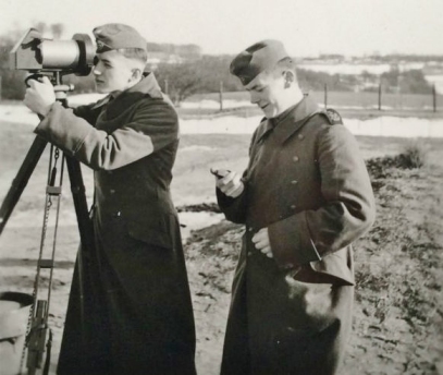
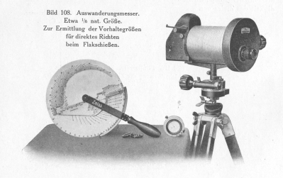
Skalentrommel; Objektiv; AM17 im Einsatz (Beobachter und Zeitstopper)
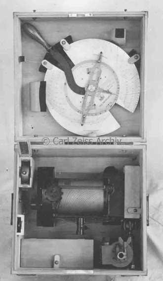
AM17 mit Stoppuuhr, Kommandoscheibe und Richtaufsatz im Transportkasten.
Scale drum; objective; AM17 in use (observer and timekeeper); AN17 with stop watch, commando disc and aiming circle in their carrying case.
(Quelle: Internet-Forum [?]; Zeiss Archiv)
| Der solide aus Messing gefertigte AM17 ist 8,4kg schwer. Er ist 30-31cm je nach Dioptrieneinstellung lang. Die 135mm lange Skalentrommel ist 102mm, die 30mm lange Strichplattendose 160mm, das Okular sowie die Augenmuschel sind 35mm, der Fokussierungring 37mm und der Drehknopf 50mm im Durchmesser. Dessen Achshalterung ist 5cm lang. Das Objektivgehäuse misst 15x65mm und ist unten 90mm und oben 35mm lang. Das analoge Visier ist 80mm lang, der Stativhalterung ist 50mm hoch. Sie wurde im Originalzsutand mit einer Flügelschraube fest gezurrt. | The AM17 made of solid brass weighs 8.4kg It is 30-31cm long depending on dioptre adjustment. The 135mm long scale drum measures 102mm, the 30mm long reticle housing is 160mm, the eyepiece as well as the eyecup are 35mm, the focusing ring 37mm, and the adjustment knob 50mm in diameter. The knob's axis is 5cm long. The objective housing measures 15x65mm. It is 90mm wide at its bottom and 35mm wide at its top. The analogue sight is 80mm long. The tripod mounting rod is 50mm tall. It was originally fastened to the tripod with a wing screw. |
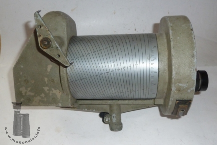
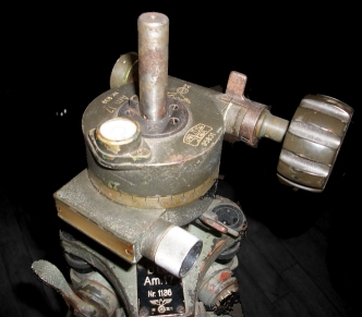
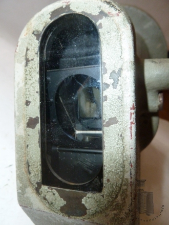
| Der AM17 wurde mit einem Richtkreis auf einem Metallstativ befestigt (s. Originalstativ im Foto und s/w Fotografie). Zur Beleuchtung der Strichplatte bei Dämmerung oder Dunkelheit gibt es ein Beleuchtungsfenster an der linken unteren Seite des runden Gehäuses. | The AM17 was mounted with an aiming circle on a tripod (see original tripod in the photo and the black and white picture). For lighting the reticle during dusk or darkness there is a small illumination window on the left lower side of the round housing. |
Fotos: Zeun; 2 aus Auerbach 1925; 9 H. Leichtfried; 12 Internet (genaue Quelle unbekannt); 13 Zeiss Archiv; 17 Internet-Forum